LAN 53-2 Supervision panel Master
Supervision panel - Master LAN 53-2 features
- 12 inputs
- Each input is programmable for NO or NC function. Positive input voltage (+24V) or 0V triggering the input
- Each input is individually programmable
- Alarm delay up to 240 seconds
- Buzzer can be programmed ON or OFF, individually per input
- 3 potential-free changeover relays alarm outputs, priority A, B or C
- Possibility to program an input to more than one priority alarm. (eg AB, AC, BC, ABC)
| E-number | Article no. | Description | Pcs/pack |
| 6390230 | LAN 53-2 | Supervision panel - Master Unit 12 inputs | 1 |
- Selectable as alarm (red diode) or operation indication (yellow diode)
- All alarm inputs have a memory and flashing function
- All incoming cables are connected to plug-in-only screw terminals that simplify assembly
- The alarm outputs will show alarm mode in the event of a power failure
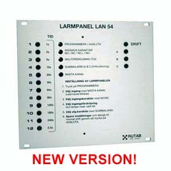
- Indication with LEDs on the front of the module
- The front of the panel is equipped with reset (acknowledgment) and LED test
- Programming instructions and connection instructions are printed on the panel (in swedish)
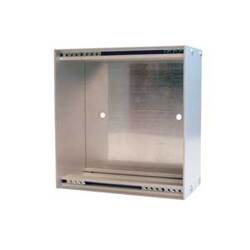
- The panel is intended to be mounted on a device cabinet, 19" subrack 3HEx28TE or our enclosure KL50
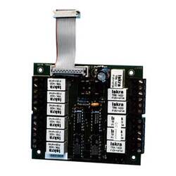
- The panel can be equipped with LAN 300PR/50 parallel board, which provides 12 galvanically free contacts for parallel transmission of alarms
Technical description
Activating an input switch is indicated by the corresponding red LED flashing after the set delay time, the acoustic alarm is triggered if selected for the input. When the set delay time for SUM-alarm has lapsed the LED for priority SUM-alarm is lit and the potential free changeover relay changes.
When acknowledging if the input is programmed as “acknowledgeable” the alarm the SUM-alarm LED and the acoustic alarm are switched off and the relay changes back to normal state. The input channel LED is changed to steady red light and remains so until the cause of alarm has been removed. If the input is programmed as “NOT acknowledgeable”, acknowledging will only silence the acoustic alarm, the SUM alarm remains active.
If additional alarm situations occur after the first alarm has been acknowledged the corresponding channel LED indicator is flashing. An alarm cause that is removed before it has been acknowledged leaves the corresponding LED flashing. Each additional alarm is indicated by a flashing channel indicator.
The inputs can be programmed as an “Indicator”, steady yellow light when active, no SUM alarm or acoustic alarm.
Supervision panel LAN53-2 can be extended with up to 6 LAN54-2. LAN53-2/LAN54-2 can be equipped with LAN300PR/50 relay-card unit.
Normal / Idle
Green "DRIFT" LED active indicating supply voltage.
Lamp test (LED)
When the TEST button is held depressed all indicators are activated for inspection.


